- Outer
- Outer boundaries are used to conceal surface components (triangles, contours, or points) occurring outside the boundary extents.
- Hide
- Hide boundaries are used to conceal surface components inside the boundary extents.
For example, consider a hide boundary to hide any interpolation occurring inside a building perimeter. - Show
- Show boundaries are used to reveal surface components inside a hide boundary. If a hide boundary was used around a building perimeter, a show boundary can be applied to reveal contours in the building’s courtyard for landscape purposes. Show boundaries can also be used to show surface areas outside an outer boundary.
- Data Clip
- A data clip is a type of boundary drawn around the extents of a site. It is used to prevent surface calculations from occurring beyond its extents. The data clip boundary should be the first component added to the surface definition. For example, if a DEM file representing the surface of an entire county will be used to create a surface, a data clip boundary can be applied first to exclude the grid information outside the construction site. Using a data clip boundary will result in smaller surfaces (fewer surface points), which will impact your file size.
One way to start defining more accurate boundaries is to first extract the boundary defining the extents of the surface to a polyline and then edit the polyline to the optimum shape. The Extract Objects From Surface utility allows you to re-create any displayed surface element (contours, border, and the like) as an independent AutoCAD entity. It is important to note that only the objects that are currently visible in the surface style can be extracted. In this exercise, you’ll extract the existing surface boundary as a starting point for creating a more refined boundary that will limit triangulation:In this example, you’ll add some breaklines that describe road and ditch features:
- Open the 0403_SurfaceBoundary.dwg or (0403_SurfaceBoundary_METRIC.dwg) file.
- Select the surface.
- From the TIN Surface contextual tab ➢ Surface Tools panel, choose Extract From Surface ➢ Extract Objects to open the Extract Objects From Surface dialog.
- Leave the Border object selected and deselect the Major Contour, Minor Contour, and Points options, as shown in Figure 1.

Figure 1: Extracting the border from the surface object. - Click OK to finish the process. Press Esc to deselect the surface.A 3D polyline has been created from the surface border.
- Pick the border 3D polyline.This polyline will form the basis for your outer surface boundary. By extracting the border polyline from the existing surface, you save a lot of time playing connect the dots along the points that are valid. Next, you’ll add this polyline into the surface as a boundary.
- In Prospector, expand the Surfaces ➢ Existing Surface ➢ Definition branches.
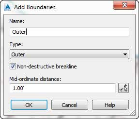
- Right-click Boundaries and select the Add option.The Add Boundaries dialog opens (see Figure 2).

Figure 2: Add Boundaries dialog. - Enter the name Outer, leave Type set to Outer, and keep the check mark next to the Nondestructive Breakline option; then click OK.
- Pick the 3D polyline border that you previously extracted.
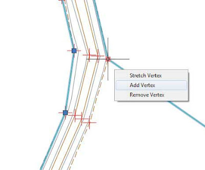
- Working your way around the site clockwise, grip-edit the polyline you created in step 6 to exclude some of the area at the northwest area of the site around the ditch where there are no points. Use the Add Vertex option from the grip menu, as shown in Figure 3.
Note that this process does not require you to use object snaps. This boundary only needs to be approximate. You will see the surface dynamically update with each grip edit since the surface is set to Rebuild Automatic.
Figure 3: Using the grips to adjust the border. - If time permits, edit the entire boundary.On a large site, you can see that this is a time-consuming process but worth the effort to clean up the site nicely (see Figure 4). Thankfully, there are other methods you can use to clean up the surface border; we will discuss these methods in later exercises.

Figure 4: A non-destructive outer boundary in action. - Save the drawing and keep it open for the next portion of the exercise.Notice in some areas along the outer boundary how the edge of the triangulation includes points shown as a square with a + symbol; these are the additional points created along the boundary line where it intersects with the triangles it crosses. The points you attempted to exclude from the surface are still being included in the calculation of elevations for this point; they are just excluded from the display and calculations. This isn’t the result you were after, so let’s fix it now.
- In Prospector, expand the Surfaces ➢ Existing Surface ➢ Definition branches and select Boundaries.A listing of the boundaries appears in the preview area of Toolspace.
- Right-click the boundary you just created and select the Delete option.
- Click OK in the warning dialog that tells you the selected definition items will be permanentlyremoved from the surface.You can dismiss Panorama if it appears.
- In Prospector, right-click Boundaries and select the Add option again.The Add Boundaries dialog appears.
- Enter the name Outer, leave Type set to Outer, and leave the check box unchecked next to the Non-destructive Breakline option; then click OK.
- Pick the revised 3D polyline again.Notice that no triangles intersect your boundary now where it does not connect points, as shown in Figure 5.

Figure 5: A destructive outer boundary in action. - In Prospector, right-click Boundaries and select the Add option again.
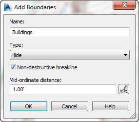
- Name the boundary Buildings and change Type to Hide. Make sure that Non-destructiveBreakline is checked, as shown in Figure 6, and click OK.

Figure 6: Adding buildings as nondestructive, hide boundaries. - Select the outer outline of the cyan building in the northwest portion of the site. Press Enter.You should now have a void in your surface where the building exists.
- Right-click Boundaries and select the Add option one last time.
- Name the boundary Courtyard, set the type to Show, and verify that Non-destructiveBreakline is checked.
- Click OK; then click the closed polyline inside the building outline and press Enter.You should now see an island of surface data inside the previously hidden location.

===o0o===
