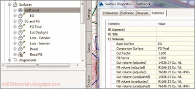
Although there are several methods that can be used to calculate earthwork volumes in Civil 3D, I will cover only one of them in this book in detail: the Volumes Dashboard. The Volumes Dashboard command is found on the Analyze tab of the ribbon. Clicking this opens Panorama, which displays the Volumes Dashboard tab. Here, you can add or create one or more TIN volume surfaces, and the cut and fill results are shown. You can also create
bounded volumes, which are smaller areas within a volume surface that might represent individual lots or project phases. You can even generate detailed reports that are displayed within a browser or within Civil 3D itself, as shown in
Figure 18.10.
 |
| Figure 18.10 A TIN volume surface named Earthwork shown in Prospector and its volume results shown in the Surface Properties dialog box. |
What’s a TIN Volume Surface?
As you may recall from
"Modeling the Existing Terrain Using Surfaces", the acronym TIN stands for
Triangular Irregular Network, which is a method of creating surfaces by drawing lines between 3D points to form triangles. A TIN surface is any surface that is created using this method. When you create a TIN
volume surface, Civil 3D superimposes one TIN surface over another and creates a point at each location where the triangle edges cross. New triangles are then created by connecting the calculated points. The resulting surface has the same distinctive triangular shapes, but instead of elevations, the values it represents are differences in elevation between the two surfaces. These differences in elevation are referred to as
cut when they are negative and
fill when they are positive.
To use the Volumes Dashboard to calculate cut and fill for the example project, follow these steps:
- Open the drawing named Calculating Volumes.dwg located in the Chapter 18 class data folder.
- Click the Analyze tab of the ribbon, and then click Volumes Dashboard.
- On the Volumes Dashboard tab of Panorama, click Create New Volume Surface.
- In the Create Volume Surface dialog box, do the following:
- For Name, select Earthwork.
- For Style, select _No Display.
- For Base Surface, select EG.
- For Comparison Surface, select FG Final.
- Click OK.
- The cut and fill results are shown in Panorama. Here, you see that the Cut Volume value is much smaller than the Fill Volume value. The project is not balanced, and the requirement for extra fill means that soil will have to be delivered to the project site. The design should be adjusted to bring it closer to balance. This can be accomplished by lowering the profiles and building pad feature lines to create more cut while eliminating the need for fill.
- Click Earthwork, and then click Add Bounded Volume. When prompted to select Bounding Object, click the parcel area label of lot 1.
- Repeat the previous step for lots 2 and 3. Click the plus sign next to Earthwork to expand the information below it. Note the individual cut and fill results that are shown for lots 1, 2, and 3.
- Change the name of Earthwork.1 to Lot 1, Earthwork.2 to Lot 2, and Earthwork.3 to Lot 3. Check the boxes next to Lots 1, 2, and 3 and then click Generate Cut/Fill Report. Your browser should open, displaying a detailed cut-and-fill report for the overall earthwork as well as the three individual lots.
Tips:If the Edit Elevations panel is not visible, click Edit Elevations.
Other Volume Methods
Civil 3D provides three additional methods for calculating cut and fill: the TIN Volume Surface, the Grading Volume Tools, and Quantity Takeoff Criteria.
- TIN Volume Surface
- You can create a TIN Volume Surface without using the Volumes Dashboard by simply using the Create Surface command and choosing TIN Volume Surface as the type. You can view the volume results for the surface by opening Surface Properties and clicking the Statistics tab.
- Grading Volume Tools
- You use the Grading Volume Tools with Grading Groups that have been assigned a volume base surface. Not only can the Grading Volume Tools report cut and fill, but they can also be used to adjust the design and even balance the design automatically.
- Quantity Takeoff Criteria
- You use Quantity Takeoff Criteria to generate section-by-section volume calculations based on a sample line group. This method is nearly always associated with a corridor model for a transportation design project.


