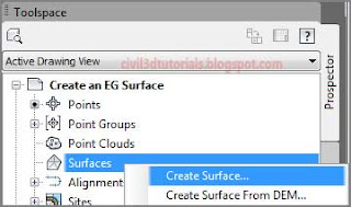
You create a surface in Prospector by simply right-clicking the Surfaces node of the tree and selecting
Create Surface, as shown in
Figure 1. The newly created surface appears in Prospector immediately, but it cannot be seen in the drawing until some data is added to it. The fundamental components of a surface are points and lines. It is your job to supply the source of the points, and Civil 3D will take care of drawing the lines. At this phase of the project, you will be using survey points as the initial source of surface point data.
 |
| Figure 1: Creating a surface from within Prospector. |
Follow these steps to create the surface from survey data:
- Open the drawing named Create an EG Surface.dwg or (Create an EG Surface.dwg (METRIC)) located in the Exercise_04 class data folder.
- On Prospector, right-click Surfaces and select Create Surface.
- In the Create Surface dialog box, enter EG in the Name field.
Tips :The EG stands for existing ground.
- For Style, select C-Existing Contours (1') (C-Existing Contours (0.5m)). Click OK to dismiss the Create Surface dialog box.
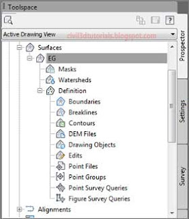
- In Prospector, expand Surfaces ➢ EG ➢ Definition. Study the items listed beneath EG in the tree (see Figure 2).
 |
| Figure 2: The contents of a surface shown in Prospector. |
- Right-click Point Groups and select Add.
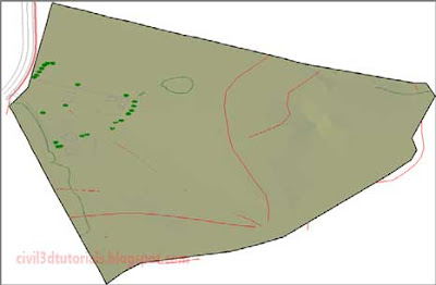
- Select Ground Shots and click OK. The surface is now visible in plan view in the form of contours and shaded 3D faces in the bottom-right 3D view.
Tips :The difference in appearance between plan view and 3D view is a function of the surface style.
- In the lower-right viewport, click Shaded and select 2D Wireframe as shown in Figure 3. The appearance of the surface will change to show the TIN lines.
 |
| Figure 3: Changing the visual style to 2D Wireframe within the lower-right viewport. |
- Change the visual style of the lower-right viewport to Conceptual, and look at the model from several different viewpoints. This way of studying the surface gives a real sense of the surface as a “solid” model in which the area inside the triangles has “substance.” It is also a great visual representation of the TIN algorithm and the surface model (see Figure 4).
 |
| Figure 4: A surface shown using the Conceptual visual style. |
Components of a Surface
As shown in
Figure 2, you can use many potential types of information to create a surface and control its shape. The following list describes each one briefly:
- Boundaries
- Boundaries are used to control where the surface is. A boundary around the edge of a surface can keep it contained within a certain area. Another type of boundary can keep a surface out of an interior area, like a pond or building.
- Breaklines
- Breaklines force TIN lines to align with them. In this way, they help to define “hard edges” such as edges of embankments, curb lines, ditch lines, and so on.
- Contours
- Usually, we think of contours as the end product of building a surface, but they can also be used as a source of data for a surface.
- DEM Files
- DEM stands for digital elevation model, and it is typically associated with large-scale mapping that has relatively low accuracy. DEMs can often be found alongside large-scale mapping data and are typically only accurate enough for rough analysis or calculations.
- Drawing Objects
- Drawing objects are AutoCAD® software entities such as lines, blocks, and even text. These items can be used to help define a surface as effectively as survey points, as long as they’ve been created at the appropriate elevations.
- Edits
- Edits aren’t actual data, but they do contribute to the makeup of a surface. There are many ways in which a surface can be edited to improve its accuracy or usability. Some of these editing methods will be covered in this chapter.
- Point Files
- You’ve already learned that a point file is a text file containing x, y, and z data. So far, you’ve used these files to create Civil 3D points in the drawing, but the same data can also be imported directly into a surface.
- Point Groups
- In "Establishing Existing Conditions Using Survey Data", you learned that one of the benefits of point groups is that they enable multiple points to be selected simultaneously. Using one or more point groups to define a surface is one of the most important and most common uses of point groups in Civil 3D.


