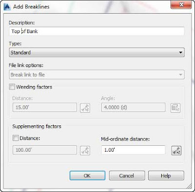
The Distance setting works like the AutoCAD measure command. When breaklines are added to a surface, Civil 3D will add additional vertices based on this increment value.
The Mid-ordinate Distance setting is applied to arc segments in your breaklines. If this setting were absent, the program would create a single breakline segment from the PC to the PT of the arc. With this setting in place, the program creates shorter segments along the arc. With each segment considered to be tiny chords, the Mid-ordinate Distance value is the resulting measurement from the midpoint of each chord to the midpoint of each segmented arc.
In this example, you’ll add some breaklines that describe road and ditch features:
- Open the 0402_SurfaceFromBreaklines.dwg file or the (0402_SurfaceFromBreaklines_METRIC.dwg) file.This drawing is similar to the drawing used in the first exercise. It contains a surface created with a point group. It also contains 3D survey figures. Without the survey database, you’ll have to add the figures conventionally, meaning through the Breakline branch of the surface.
- Inspect the drawing by panning and zooming along the linework.Notice that the TIN lines are not drawn along the figures representing the edge of pavement, centerline of roads, flowline of ditches, and top of banks.
- Select and then right-click one of the brown figures representing the top of bank, and choose the Select Similar option.The tooltip will indicate a figure prefix style of TB.All the brown figures representing the tops of banks are now highlighted.
- In Prospector, expand the Surfaces ➢ Existing Surface ➢ Definition branches.
- Right-click Breaklines and select the Add option.
- Enter the description Top of Bank and leave all other settings at their default, as shown in Figure 1.

Figure 1: Entering a description in the Add Breaklines dialog. - Click OK to accept the settings and close the dialog.You can dismiss Panorama if it appears.
- Repeat steps 3–7 for figures DL (Flowline of Ditch), BB (Bottom of Bank), CL (Centerline of Road), and EP (Edge of Pavement).
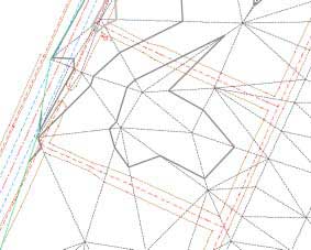
- Zoom extents and notice that the TIN lines are now running along the survey figures now acting as breaklines.
The Add Breaklines dialog appears.
 |  |
| Figure 2: Existing surface with contours displayed before breaklines are added (left) and after (right) | |
===o0o===
