As you place points using these tools, a few general rules apply to all of them. If you place a point on an object with elevation, the point will automatically inherit the elevation of the object. If you use the surface options, the point will automatically inherit the elevation of the surface you choose.
- Miscellaneous Point-Creation Options
- The options in the Miscellaneous category allow you to create a point by manually specifying its location onscreen or relative to existing basic objects in the drawing. Also within this category are the options to convert data from AutoCAD points or Softdesk point blocks (see Figure 1).
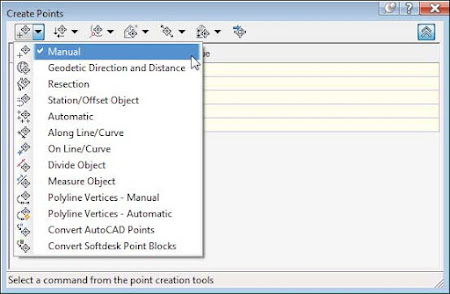
Figure 1: Miscellaneous point-creation options. - Intersection Point-Creation Options
- The options in this category allow you to place points based on the calculated intersection of specific items without defining construction lines. For example, if you needed a point at the intersection of two bearings, you could draw two construction lines using the Bearing Distance transparent command, manually place a point where they intersect, and then erase the construction lines. By using the tools within this category, you could use the Direction/Direction tool to accomplish the same without using construction lines (see Figure 2).
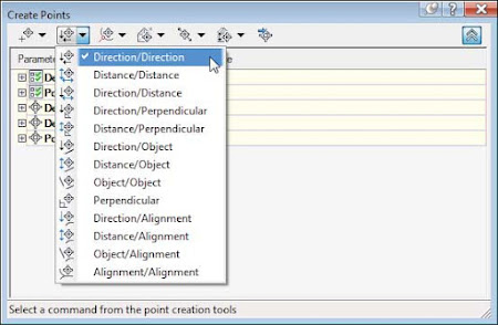
Figure 2: Intersection point-creation options. - Alignment Point-Creation Options
- The options in the Alignment category are designed for creating stakeout points based on a road centerline or other alignments. You can also set profile geometry points along the alignment using a tool from this menu. See Figure 3.
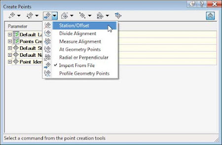
Figure 3: Alignment point-creation options. - Surface Point-Creation Options
- The options in the Surface category let you set points that harvest their elevation data from a surface. Note that these are points, not labels, and therefore aren’t dynamic to the surface. You can set points manually, along a contour or a polyline, or in a grid (see Figure 4).
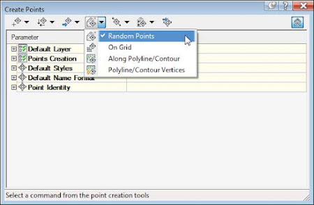
Figure 4: Surface point-creationoptions. - Interpolation Point-Creation Options
- The Interpolation category lets you fill in missing information from survey data or establish intermediate points for your design tasks. For example, suppose your survey crew picked up centerline road shots every 100’ (30 m) and you’d like to interpolate intermediate points every 25’ (8 m). Instead of doing a manual slope calculation, you could use the Incremental Distance tool to create additional points (see Figure 5).
Another use would be to set intermediate points along a pipe stakeout. You could set points for the starting and ending inverts and then set intermediate points along the pipe to assist the field crew.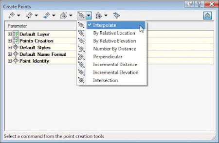
Figure 5: The Interpolation point-creation options. - Slope Point-Creation Options
- The Slope category allows you to set points between two known elevations by setting a slope or grade. Similar to the options in the Interpolation and Intersection categories, these tools save you time by eliminating construction geometry and hand calculations (see Figure 6).
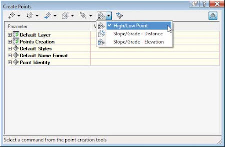
Figure 6: Slope point-creation options.
Using the Automatic – Object Option
The Description option in the point settings Automatic – Object can be used only when placing points along an alignment. For example, when you’re placing points using the At Geometry Points option, the point will inherit the alignment’s name, the station value of the point, and the type of geometry as its description.For all other point-placement options, Automatic – Object will behave the same as Automatic.
- Point Settings
- Importing Points from a Text File
- Converting Points from Non–Civil 3D Sources
- A Closer Look at the Create Points Toolbar
