In this exercise, you’ll learn how to create points along a parcel segment and along a surface contour:
- Open the 0305_PointCreation.dwg or (0305_PointCreation_METRIC.dwg) file.
Note that the drawing includes alignments, a series of parcels, and an existing ground surface. - On the Home tab ➢ Create Ground Data panel ➢ Points menu, click Point Creation Tools.
- If it is not already expanded, click the chevron icon on the right to expand the dialog.
- Expand the Points Creation category.
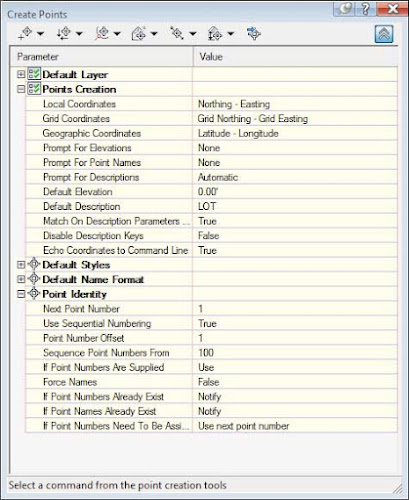
- Change the Prompt For Elevations value to None and the Prompt For Descriptions value to Automatic by clicking in the respective cell in the Value column, clicking the down arrow, and selecting the appropriate option.
- Enter LOT for Default Description (see Figure 1).
 |
| Figure 1: Point-creation settings in the Create Points dialog. |
This will save you from having to enter a description and elevation each time. Because you’re setting stakeout points for rear lot corners, you will disregard elevation for now. - Select the Automatic tool from the Miscellaneous flyout (the first icon flyout on the top left of the Create Points toolbar).
- Focusing on the area at end of the cul-de-sac you will find the parcel named BCG_Lots : 1. Select that parcel by selecting one of its segments. Press ↲.
- Press Esc to exit the command.
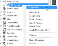
A point is placed at each property corner and at the endpoints of each curve. Even if the marker is visible, you will not see the point label. The reason is that since there is no description key within the set to manage the LOT key, the point’s labeling is managed by the settings of the point group it belongs to. It belongs to the only point group defined in the drawing, the default _All Points, which has by default the labeling for its points set to <none>. - Right-click the _All Points group within the Point Groups collection in the Prospector tab of Toolspace and choose Properties, as shown in Figure 2.
 |  |
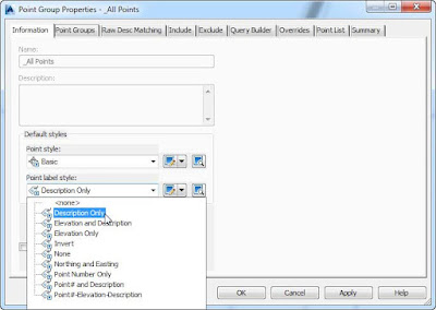
| Figure 2: To assign a label style to the _All Points group, access its properties (left) and assign the desired style (right) |
- Choose Description Only from the Point Label Style drop-down on the Information tab of the Points Group Properties – _All Points dialog.
- Click OK to exit the dialog.
- Select the Measure Object tool from the Miscellaneous flyout.
- Click anywhere on the parcel boundary for BCG_Lots : 29.
After you select the parcel boundary for BCG_Lots : 29, this tool prompts you for starting and ending stations. - Press ↲ twice to accept the default starting and ending stationing and again to accept the default of 0 for the offset.
- At the Interval prompt, enter 25 if you are working in feet and 10 if you are working in metric units.
- Press Enter to continue.
- Press Esc to exit the command.
A point is placed at 25’ (10 m) intervals along the property boundary.
Next, you’ll experiment with the Direction/Direction option from the Intersection Point flyout. Be sure your Endpoint Osnap is on for the next steps.
Let’s focus now on BCG_Lots : 33.
- Click the Direction/Direction icon and click the northwest endpoint of the parcel line that this property shares with BCG_Lots : 1.
- Click the opposite endpoint of the segment that the two of them share to establish the direction of the line.
The yellow arrow that appears indicates the direction.
- Press ↲ to specify the default of 0 for the offset.
- Click the southeast corner of BCG_Lots : 33 on the property line that this property shares with BCG_Lots : 34 and then click the endpoint of the same property line to establish the second direction.
- Press ↲ to specify a zero offset.
A point is generated where the two lines would intersect if they were to be extended.
Press Esc to exit the command. - In the point-creation settings, change Prompt For Descriptions to Automatic – Object.
- From the Alignments flyout, choose At Geometry Points.
- When prompted for an alignment, select the green centerline alignment, ROAD G.
You are now prompted for a profile.
- Select FG-ROAD G from the drop-down and click OK.
- Press ↲ twice to confirm the starting and ending station values along the alignment.
- Press Esc to exit the command.
You should now see points whose names are based on alignment information.
- Return to the Point Settings category and change Prompt For Elevations to Manual and Default Description to EG.
The next round of points you’ll set will be based on the existing ground elevation.
- Select the Along Polyline/Contour tool in the Surface flyout.
- When prompted with Distance between points<10.0000>, key in 9 for feet (3 formeters) and press Enter to continue.
- Click the magenta polyline inside BCG_Lots : 1.
Notice that the points will be created, but their label style will not use the default of the _All Points group. You will know why if you look at the description key for the EG code.
- Press Esc to exit the command, close the Create Points toolbar, save the drawing, and keep it open for the next exercise.
You can go ahead and experiment with the variety of point-creation tools available.
You can compare the completed file as the name
0305_PointCreation_FINISHED.dwg or
(0305_PointCreation_METRIC_FINISHED.dwg).


