As you may have noticed in
Figure 15.8, there is also a Profile Layout Tools command. The editing tools available for pressure networks in profile view are a bit more numerous when compared to gravity networks. For example, with pressure networks, you can add new pipes, add fittings, extend pipes, and perform several other functions that are not possible with gravity pipes. When you click the Profile Layout Tools command, the Pressure Network Profile Layout ribbon tab opens
(see Figure 15.9); it provides many useful editing commands that are carried out in profile view.
 |
| Figure 15.9 The specialized ribbon tab for pressure pipe layout in profile view. |
To use the Profile Layout Tools command to make edits to your pressure network design, follow these steps:
- Open the drawing named Editing Pressure Networks Using the Profile Editing Tools.dwg located in the Chapter 15 class data folder.
- Click the new pipe that runs from circle H to circle F2 and the tee fitting at Circle F2. Click Draw Parts In Profile on the ribbon, and click one of the grid lines within the Jordan Court profile view. The new pipe and fitting will now be drawn in the profile view. Notice the tee connection and the short pipe stub located down and to the left of the new pipe. This is the location where the new waterline will connect to the existing waterline.
- With one of the pipes or fittings selected, on the ribbon select Edit NetworkProfile Layout Tools.
- Next to Add Bend, select 6 INCH (150mm) ELBOW 45 DEG. Then click Add Bend.
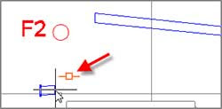
- In the upper-right viewport, place your cursor near the right end of the short pipe segment located just below the red circle. When the glyph appears, as shown in Figure 15.10, click the pipe. Click COunterclockwise on the command line. A new 45° bend should appear. It may look odd in profile view because of the vertical exaggeration. If you zoom in to the new fitting in the 3D view, it will look more like you would expect.
 |
| Figure 15.10 A glyph indicating the proper connection of a pipe to a fitting. |
- Verify that 6 INCH (150mm) DUCTILE IRON is selected as the current pipe size and click Add Pressure Pipe. When prompted for the part at the start of the range, click the newly created elbow.
- When prompted for the part at the end of the range, click the pipe to the right of the red circle. Click Yes when asked if you want to continue.
- Click the newly created elbow, and then snap to the center of the red circle located above the new bend.
- Click Add Bend; then click the end of the newly created pipe, making sure that the proper glyph is showing, as shown in Figure 15.10. Click Clockwise on the command line to invoke the Clockwise option. Another 45° bend is created.
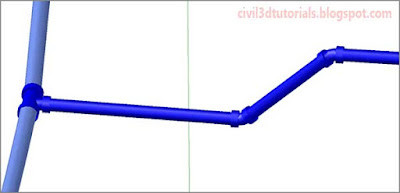
- Click the pipe just to the right of the newly created bend. Click the upright triangle grip at the left end of the pipe and drag it toward the new bend. Click the newly created bend to connect the pipe to it. In the 3D view, you can now see the complete design of the connection between the existing and proposed water mains (see Figure 15.11).
Tips:You could have also done this step using the 3D view or the plan view.
 |
| Figure 15.11 The connection of the proposed waterline to the existing waterline, shown in a 3D perspective. |
- On the ribbon, click Break Pipe. Locate the two vertical red lines on the first pipe segment, and click where the red line on the left crosses the top of the pipe.
- Repeat the previous step for the red line on the right.
- On the ribbon, click Delete Part. Click the pipe segment between the red lines.
- Click Add Appurtenance, and then click the left side of the gap created by deleting the pipe segment in the previous step. A valve symbol should appear in the profile view.
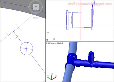
- Click the pipe on the right side of the gap to display its grips. Click the upright triangle grip, and drag it toward the new valve. Click when the glyph appears, indicating that a connection is going to be made. View the tee and valve assembly in the lower-right viewport (see Figure 15.12).
 |
| Figure 15.12 The connection of the proposed waterline to the existing waterline, shown in plan, profile, and 3D perspective. |
- Press Esc to clear all of the selections in the drawing. In profile view, pan to the right and select the long pipe. Click Follow Surface on the Pressure Network Profile Layout tab of the ribbon.
- Press Enter; then type 4.5 (1.5) at the command line when prompted for depth below surface. Press Enter to complete the command. The pipe has been broken into segments so that it can maintain a constant depth below the surface.


