
Fitting – Square Grip – Plan ViewThis grip changes the location of the fitting without changing its rotation. As the fitting is moved, the ends of any pipes that connect to it will move with it.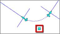
Fitting – Arrow Grip – Plan ViewThis grip changes the direction of the fitting by flipping it around the axis of the connecting pipe.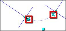
Fitting – Diamond Grip – Plan ViewThis grip slides the fitting along the pipe that it is connected to without changing the rotation angle of the fitting.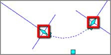
Fitting – Plus Grip – Plan ViewThis grip creates a new pipe projecting from the end of the fitting with the angle restricted to the allowable deflection at the joint. This grip does not appear in a location where a pipe is already connected.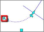
Fitting – Diamond Grip – Profile ViewThis grip changes the elevation of the fitting.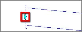
Pipe Endpoint – Square Grip – Plan ViewThis grip changes the location of one end of the pipe without changing the location of the other. It is only available if neither end of the pipe is connected to a fitting.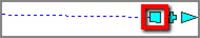
Pipe Endpoint – Diamond Grip – Plan ViewThis grip swings the pipe around a fitting at the opposite end. A graphic will display the allowable deflection, but will not restrict movement to stay within it. This grip will not change the length of the pipe.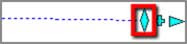
Pipe Endpoint – Plus Grip – Plan ViewThis grip creates a new fitting and pipe projecting from the end of the pipe you’ve selected. The angle of the new pipe will be restricted to the allowable angles as per the fittings in the parts list. This grip does not appear in a location where a fitting is already connected.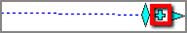
Pipe Endpoint – Triangular Grip – Plan ViewThis grip changes the length of the pipe while maintaining the angle of the pipe and the location of the opposite end. If the pipe is curved, it will maintain the radius of the pipe while extending it along its own curvature.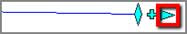
Pipe Midpoint Grip – Plan ViewFor a straight pipe, this grip changes the location of the pipe without changing its rotation. It will disconnect the pipe from any fittings it is attached to. For a curved pipe with a connection at both ends, this grip changes the radius of the curve without changing the location of either endpoint. If one or both of the ends is not connected, it will work the same as if it is a straight pipe.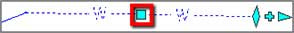
Pipe Endpoint Grips – Profile ViewThese grips change the elevation of a pipe at its endpoint. The diamond-shaped grip at the top sets the crown (top of the inside wall) elevation. The diamond-shaped grip at the bottom sets the invert (bottom of the inside wall) elevation. The triangular grip sets the centerline elevation. These grips can be used in conjunction with the AutoCAD Dynamic Input feature to view the elevation or even type it in. They do not change the horizontal location of the pipe’s endpoint.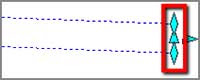
Pipe Endpoint – Triangle Grip – Profile ViewThis grip changes the length of the pipe while holding its slope.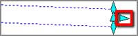
Pipe Midpoint – Square Grip – Profile ViewThis grip changes the elevation of the pipe without changing its slope. It does not affect the location of the pipe in plan view. It will disconnect the pipe from any fittings or appurtenances it is connected to.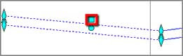
Pipe Midpoint – Circular Grip – Profile ViewThis grip curves the pipe by holding the endpoints and forcing it to pass through the new location that you select for the grip. Movement is not restricted based on allowable deflections.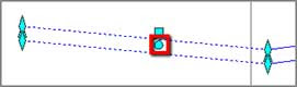
To use grips to edit the pipes and fittings in your drawing, follow these steps:- Open the drawing named Editing Pressure Networks Using Grips.dwg located in the Chapter 15 class data folder.
- In the left viewport, zoom in to the circle marked D1 and click the 90 elbow fitting near its center. Click the fitting, and then click the square grip.
- Snap to the center of the circle marked D2. The fitting moves to the new location along with the ends of the two pipes that are connected to it. The geometry of the fitting looks a bit odd at the moment because the fitting should be changed to a 45 elbow. This will be addressed in a later exercise.
- In the lower-right viewport, click the curved pipe between E and F1; then click the triangular grip at circle F1. Snap to the center of circle F2.
- Click the plus sign grip at circle F2. On the ribbon, select EG as the surface and change the Cover value to 4.5 (1.5). Select 6 INCH (150mm) DUCTILE IRON as the pipe size, and snap to the center of circle G.
- Press Esc to end the current command, and clear any selections in the drawing. Click the pipe between E and F2, and then click Draw Parts In Profile on the Pipe Networks: Water Main ribbon tab.
- Click one of the grid lines of the Jordan Court profile view. The water pipe should appear in the profile view.
- Press Esc to clear the current selection. Select all pipes and fittings from circle E to circle A; then use the Draw Parts In Profile command to add them to the profile view. The waterline should now appear in the profile view, as shown in Figure 15.7.
- In the profile view, click the second fitting from the left located near station 2+75 (0+080). Click the diamond-shaped grip. If Dynamic Input is turned off, turn it on by clicking the icon at the bottom of your screen.
- Zoom out until you can see the Dynamic Input elevation value for the grip. Type 184 (55.45) and press Enter.
- Pan to the right and click the long pipe at the right end of the water main. Click the circular grip; then click a point slightly above the pipe. The pipe will curve upward so that it passes through the point you selected.
Tips:The location of the next fitting will be outside the area covered by the Road FG surface, and it will therefore be based on EG surface elevations.
Tips:Notice how the end of the pipe is not located at the elevation of the center of circle G, even though that’s where you snapped. Civil 3D calculated the elevation based on the surface and the Cover value you specified.

 |
| Figure 15.7 The Water Main pressure pipes and fittings shown in profile view. |
- Editing Pressure Networks Using Grips
- Checking Design and Depth
- Editing Pressure Networks Using the Plan Layout Tools
- Editing Pressure Networks Using the Profile Layout Tools