Additional Exercise;

In this exercise, you learned how to use Civil 3D to shape the land. You saw how you can use feature lines to draw new breaklines to represent the edges of landforms such as curbs, ditches, and embankment edges. You should now have an understanding of the tools that are used to create these feature lines and also to modify them.

For cases where you need Civil 3D to calculate the locations and elevations of new breaklines, you learned how to use grading objects to create complex grading models, such as the pond that you built and modified in the last two exercises. You have learned how the dynamic nature of grading objects enables you to make edits and generate surfaces with minimal time and effort.

Use the following additional exercise to apply what you have learned to several similar designs.

Open the drawing named Grading Beyond.dwg located in the Chapter 17 class data folder.This drawing contains an alternate layout for the detention pond in a different location.
Complete the following tasks:
  1. Create a pond design similar to the one you created in the last two exercises. A feature line has been provided between lots 62 and 66, which represents the top inside edge of the pond.
  2. Continue grading lots 27, 28, and 29 in the same manner that you graded lots 25 and 26.
  3. Create a surface from the feature lines that are used to define the grading for lots 25 through 29.

Because of the dynamic nature of grading objects, any edits to a feature line that serves as a grading object baseline will automatically trigger an update of the grading object. This makes most grading object editing fairly easy. In addition, there are two tools that you can use to edit the criteria that were used to create the grading object: Grading Editor and Edit Grading. The Grading Editor command opens Panorama, enabling you to edit the criteria in a table format. The Edit Grading command is a command-line interface.

To edit grading objects in your drawing, follow these steps:
  1. Open the drawing named Editing Grading Objects.dwg located in the Chapter 17 class data folder.
  2. Click the green feature line that represents the inside edge of the pond berm. Click the grip at the northeast corner, and then use the Center object snap to select the center of the red circle to the east. The grading object will recalculate based on the new shape of its baseline. The grading group surface will also update, enabling the contours to match the new shape as well.
  3. With the feature line still selected, click Raise/Lower on the Edit Elevations panel of the ribbon. You will be prompted to specify an elevation difference.
    Tips:If the Edit Elevations panel is not visible, click Edit Elevations on the ribbon.
  4. Type -1 (-0.3) and press Enter to lower the feature line by 1' (0.3m). The entire grading group and associated surface will update. Now the bottom of the pond is too low and will need to be raised.
  5. Press Esc to clear the selection of the feature line. On the Modify tab of the ribbon, click Grading.
  6. Click Grading Editor, and then click a point within the inside embankment of the pond. The edges of the grading object are highlighted to help you make your selection.
  7. On the Grading Editor tab of Panorama, type -6 (-1.83) for Relative Elevation and press Enter. The grading group is updated and the pond bottom has been raised by 1' (0.3m).
  8. On the Grading tab of the ribbon, click Edit Grading. Click a point within the area representing the top of the berm.
  9. When you’re prompted to specify a distance, type 12 (3.6) and press Enter.
  10. Press Enter twice to accept the default format of Grade and the default grade of 2 percent. Press Enter a third time to end the command. The grading group and surface update to accommodate the wider berm. The pond model now reflects the wider berm along with the shape and elevation changes made in earlier steps Figure 17.14.
    The pond model after several edits
    Figure 17.14  The pond model after several edits

You begin creating a grading object by launching the Grading Creation Tools command. This opens the Grading Creation Tools toolbar (see Figure 17.10), which is similar to the Alignment Layout Tools and the Network Layout Tools toolbars that you used in previous chapters. Like those toolbars, the Grading Creation Tools toolbar provides the commands to configure your design, create new design objects, and edit those objects.
The Grading Creation Tools toolbar
Figure 17.10  The Grading Creation Tools toolbar
To create grading objects in your drawing, complete the following steps:
  1. Open the drawing named Creating Grading Objects.dwg located in the Chapter 17 class data folder. The drawing is zoomed in to the proposed location of a stormwater detention pond. You will use grading objects to build a model of the pond, starting with the green feature line that represents the top inside edge of the pond.

    I Thought Detention Was a Bad Thing

    The pond that you design in this exercise is referred to as a detention pond. Its function is to slow down the release of stormwater to the same rate that existed prior to development. When it rains, runoff is collected by the inlets and conveyed to the pond through underground pipes. The pond outlet is restricted to reduce the flow of water. This causes the water to back up, hence the need for a pond to detain it. After the storm is over, the water will stay in the pond for a bit until it empties out.

    What’s the reason for all this? Before grass, soil, and forest were replaced with pavement, runoff water was released from this area of land at a relatively slow rate. Now, less of the water is being absorbed, and it is traveling much faster along the pavement and concrete that carries it. This increase in flow and velocity causes erosion damage and must be mitigated. A common way to accomplish this mitigation is by including a pond in your design.
  2. On the Home tab of the ribbon, click GradingGrading Creation Tools. The Grading Creation Tools toolbar will open.
  3. Click Set The Grading Group. The Site dialog box will open.
  4. Select Pond and click OK. The Create Grading Group dialog box will open.
  5. Type Pond in the Name field. Verify that Automatic Surface Creation is turned on, and then click OK. The Create Surface dialog box opens.
  6. Click OK to dismiss the Create Surface dialog box.
  7. Expand the criteria list and choose Grade To Relative Elevation, as shown in Figure 17.11.
    Selecting grading criteria on the Grading Creation Tools toolbar
    Figure 17.11  Selecting grading criteria on the Grading Creation Tools toolbar
  8. Expand the list of creation commands and click Create Grading, as shown in Figure 17.12. You will be prompted to select a feature.
    Selecting the Create Grading command
    Figure 17.12  Selecting the Create Grading command
  9. Click the green feature line. When you’re prompted to select the grading side, click a point inside the feature line.
  10. Press Enter to apply the grading to the entire length. You are prompted for the relative elevation value.
  11. Type -7 (-2.13) and press Enter. When you’re prompted for format, press Enter to accept the default of Slope.
  12. When you’re prompted for slope, type 3 and press Enter to apply a slope of 3:1. After a pause, a new grading object is created that represents the inside slope of the pond. A surface is also created, and it is displayed as red and blue contours in plan view.
  13. Expand the list of creation tools and select Create Infill. Click a point near the center of the pond. The 3D view now shows that the pond has a bottom.
    Tips:The infill created in step 13 is a special type of grading object that simply fills a void in a grading group. It does not provide additional elevation points; instead, it enables the grading group surface to extend across an open area. An infill can be placed in any closed area created by one or more feature lines that occupy the same site.
  14. Select the Grade To Distance criteria.
  15. Expand the list of creation tools and select Create Grading. When you’re prompted to select a feature, click the same green feature line that you picked in step 9.
  16. When prompted for the grading side, pick a point outside the pond. Press Enter to apply the grading to the entire length.
  17. Press Enter to accept the default distance of 10.000' (3.000m). When you’re prompted for format, type G to invoke the Grade option and press Enter.
  18. Press Enter to accept the default grade of 2 percent. A new grading object is created that represents the berm of the pond.
  19. On the Grading Creation Tools toolbar, click Set The Target Surface. In the Select Surface dialog box, select EG and click OK.
  20. Select the Grade To Surface criteria. Expand the list of creation tools and select Create Grading.
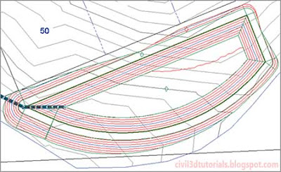
  21. Click the outside edge of the grading object created in step 18. Press Enter at all prompts to accept the default values. This creates a 3:1 daylight slope that intersects with the EG surface. This also completes the surface for the pond as indicated by the red and blue contours (see Figure 17.13).
    Contours representing the pond design
    Figure 17.13  Contours representing the pond design.

Like feature lines, grading objects must exist within a Civil 3D site. When two or more grading objects occupy the same site, there is potential for them to interact. There is also the potential for grading objects to interact with other feature lines in the same site. This interaction can benefit some designs, but there are cases where this interaction will cause the design to be incorrect. Therefore, it is important to proactively manage sites while you’re working with grading objects and feature lines.
A grading group is a named collection of grading objects that enables you to perform certain important functions with multiple grading objects simultaneously. For example, you can create a surface from a grading group or calculate cut and fill values by comparing a grading group to a surface in the drawing.
The design parameters that you apply to a grading object can require multiple pieces of information. For this reason, Civil 3D utilizes a system of grading criteria, which enables you to refer to a set of instructions by name rather than having to re-specify them for each grading design. For example, you might have criteria with the name Curb, which instruct Civil 3D to project upward at a very steep slope for a very short distance. Similar criteria with names like Pond Embankment, Ditch Slope, and so on might be created alongside your Curb criteria. You can organize your named grading criteria even further by grouping them into grading criteria sets. For example, you might have one criteria set for pond grading, another for parking lots, another for athletic fields, and so on. Figure 17.9 shows grading criteria that would be used to create the inside slope of a pond.
An example of grading criteria
Figure 17.9  An example of grading criteria typically used for the inside slope of a pond