You begin creating a grading object by launching the Grading Creation Tools command. This opens the Grading Creation Tools toolbar
(see Figure 17.10), which is similar to the Alignment Layout Tools and the Network Layout Tools toolbars that you used in previous chapters. Like those toolbars, the Grading Creation Tools toolbar provides the commands to configure your design, create new design objects, and edit those objects.
 |
| Figure 17.10 The Grading Creation Tools toolbar |
To create grading objects in your drawing, complete the following steps:
- Open the drawing named Creating Grading Objects.dwg located in the Chapter 17 class data folder. The drawing is zoomed in to the proposed location of a stormwater detention pond. You will use grading objects to build a model of the pond, starting with the green feature line that represents the top inside edge of the pond.
I Thought Detention Was a Bad Thing
The pond that you design in this exercise is referred to as a detention pond. Its function is to slow down the release of stormwater to the same rate that existed prior to development. When it rains, runoff is collected by the inlets and conveyed to the pond through underground pipes. The pond outlet is restricted to reduce the flow of water. This causes the water to back up, hence the need for a pond to detain it. After the storm is over, the water will stay in the pond for a bit until it empties out.
What’s the reason for all this? Before grass, soil, and forest were replaced with pavement, runoff water was released from this area of land at a relatively slow rate. Now, less of the water is being absorbed, and it is traveling much faster along the pavement and concrete that carries it. This increase in flow and velocity causes erosion damage and must be mitigated. A common way to accomplish this mitigation is by including a pond in your design.

- On the Home tab of the ribbon, click GradingGrading Creation Tools. The Grading Creation Tools toolbar will open.
- Click Set The Grading Group. The Site dialog box will open.
- Select Pond and click OK. The Create Grading Group dialog box will open.
- Type Pond in the Name field. Verify that Automatic Surface Creation is turned on, and then click OK. The Create Surface dialog box opens.
- Click OK to dismiss the Create Surface dialog box.
- Expand the criteria list and choose Grade To Relative Elevation, as shown in Figure 17.11.
 |
| Figure 17.11 Selecting grading criteria on the Grading Creation Tools toolbar |
- Expand the list of creation commands and click Create Grading, as shown in Figure 17.12. You will be prompted to select a feature.
 |
| Figure 17.12 Selecting the Create Grading command |
- Click the green feature line. When you’re prompted to select the grading side, click a point inside the feature line.
- Press Enter to apply the grading to the entire length. You are prompted for the relative elevation value.
- Type -7 (-2.13) and press Enter. When you’re prompted for format, press Enter to accept the default of Slope.
- When you’re prompted for slope, type 3 and press Enter to apply a slope of 3:1. After a pause, a new grading object is created that represents the inside slope of the pond. A surface is also created, and it is displayed as red and blue contours in plan view.
- Expand the list of creation tools and select Create Infill. Click a point near the center of the pond. The 3D view now shows that the pond has a bottom.
Tips:The infill created in step 13 is a special type of grading object that simply fills a void in a grading group. It does not provide additional elevation points; instead, it enables the grading group surface to extend across an open area. An infill can be placed in any closed area created by one or more feature lines that occupy the same site.
- Select the Grade To Distance criteria.
- Expand the list of creation tools and select Create Grading. When you’re prompted to select a feature, click the same green feature line that you picked in step 9.
- When prompted for the grading side, pick a point outside the pond. Press Enter to apply the grading to the entire length.
- Press Enter to accept the default distance of 10.000' (3.000m). When you’re prompted for format, type G to invoke the Grade option and press Enter.
- Press Enter to accept the default grade of 2 percent. A new grading object is created that represents the berm of the pond.
- On the Grading Creation Tools toolbar, click Set The Target Surface. In the Select Surface dialog box, select EG and click OK.
- Select the Grade To Surface criteria. Expand the list of creation tools and select Create Grading.
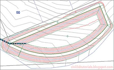
- Click the outside edge of the grading object created in step 18. Press Enter at all prompts to accept the default values. This creates a 3:1 daylight slope that intersects with the EG surface. This also completes the surface for the pond as indicated by the red and blue contours (see Figure 17.13).
 |
| Figure 17.13 Contours representing the pond design. |


