A point group is a collection of points that results when a criteria-based filter is applied to the point data in the drawing. For the filter criteria you can use any point property or combination of properties such as description, elevation, and point number, or you can select specific points in the drawing.
You will see that a point group is already created by default in any Civil 3D drawing: the _All Points group. This group contains all points in the drawing regardless of filter criteria.
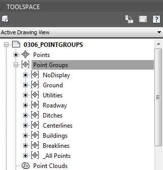
This group cannot be renamed or deleted, nor can it have its properties modified to exclude any points. Therefore, you should create point groups for collections of points you might want to separate from others, as shown in Figure 1.
 |
| Figure 1: An example of useful point groups in Prospector. |
In this exercise, you’ll learn how to use point groups to separate points into usable categories:
- Open the drawing 0306_PointGroups.dwg or (0306_PointGroups_METRIC.dwg).
- In Prospector, right-click Point Groups and select New.
- On the Information tab, name the point group Breaklines.
- Set Point Style to Basic Circle.
- Set Point Label Style to Description Only
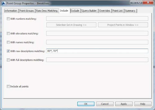
- Switch to the Include tab and place a check mark next to With Raw Descriptions Matching.
- In the With Raw Descriptions Matching field, enter BB*,TB*.The asterisk acts as a wildcard to include points that may have additional information after the description. You are adding multiple descriptions by separating them with a comma, as shown in Figure 2.

Figure 2: The Include tab of the Breaklines point group properties. - Switch to the Overrides tab.
- Place check marks next to Style and Point Label Style, as shown in Figure 3.
Doing so ensures that the point group, instead of the description keys, will control the styles.
Figure 3: Overrides force the display of the points to use styles assigned by the point group rather than the description key. - Switch to the Point List tab and examine the points that have been picked up by the group. Only points beginning with BB and TB should appear in the list.
- Click OK.
- Again, right-click Point Groups and select New.
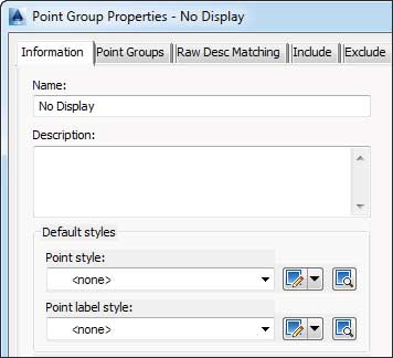
- On the Information tab, name the group No Display, as shown in Figure 4.

Figure 4: Most drawings should contain a No Display point group with styles set to <none>. - Set both Point Style and Point Label Style to <none>.
- Switch to the Include tab, and at the bottom of the dialog, put a check mark next to Include All Points.
- Switch to the Overrides tab and place a check mark next to Style and Point Label Style.
- Click OK.All the points are hidden from view as a result of the point group.
- Create another point group called Topo.
- Set Point Style to Basic Cross and Point Label Style to Elevation and Description.
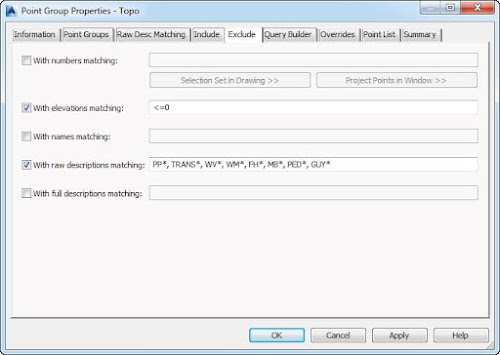
- Switch to the Exclude tab and place a check mark next to With Elevations Matching.
- Enter <=0 in the accompanying field.
- Place a check mark next to With Raw Descriptions Matching.
- Type PP*, TRANS*, WV*, WM*, FH*, MB*, PED*, GUY* in the accompanying field, as shown in Figure 5, and click OK.
You may need to use the AutoCAD REGEN command to refresh the graphic and show your points again.
Figure 5: Use Exclude to create a Topo point group. - Save the drawing.
Point groups will dictate point and label styles only if the description key set does not manage those properties. If a description key set manages the point and label styles for the point, then the only way to override it is to use the settings in the Overrides tab for the point group.
For example, if you have a point group that encompasses all your ground shots and the description key set defines their marker as an X, you could change that representation to + for the point group on the Overrides tab by toggling the setting for Point Style and selecting the style that has the desired representation. So, in this case, these settings take control of the styles away from the description key and place it with the point group.
===o0o===
