This exercise will give you a chance to work through a basic project. Unless otherwise specified, don’t change the dialog box default options.
- Open the drawing 0103_QuickStart.dwg or (0103_QuickStart_METRIC.dwg).
- From the Home tab ➢ Create Ground Data panel, click the Import Survey Data.
- Click Create New Survey Database.
- In the New Local Survey Database dialog, name the new database and click OK.
- Click Next.
- In the Import Survey Data – Specify Data Source dialog, follow these steps:
- Set Data Source Type to Point File.
- Click the plus sign to the right of the Selected Files box.
- Set your Files Of Type option to Text/Template/Extract File (*.txt), browse for 0103_QuickStart.txt or (0103_QuickStart_METRIC.txt), and click OK.
- Verify that Specify Point File Format is set to PNEZD (Comma Delimited).
- Click Next.
- In the Import Survey Data – Specify Network dialog, click Next.
- In the Import Survey Data – Import Options dialog, follow these steps:
- Fill in the check box for Process Linework During Import.
- Fill in the check box for Insert Network Object.
- Fill in the check box for Insert Figure Objects.
- Fill in the check box for Insert Survey Points.
- Leave all other options at the default settings and click Finish.
The first thing you will notice is that when the import process is complete, Civil 3D zooms to the area of the processed data. Also, did you notice that shots with the description TOPO look different from other survey points in the drawing? - Expand the Point Groups branch on Prospector and notice that the TOPO point group that you will be incorporating in the existing surface shows an exclamation mark.This indicates that the point group needs to be updated. To have all the point groups updated, right-click the Point Groups collection and select the Update option, as shown on the left of the following figure. After updating, the list of point groups will appear, as shown on the right side of the following figure.
- From the Home tab of the ribbon, find the Create Ground Data panel and choose Surfaces ➢ Create Surface.
- In the Create Surface dialog, change the name to Existing and click OK.
- In the Prospector tab of Toolspace, expand Surfaces ➢ Existing ➢ Definition.
- Right-click Point Groups and select Add.
- Select TOPO and click OK.
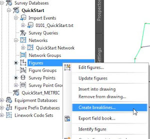
At this point you should see contours and the surface border. - On the Survey tab of Toolspace, right-click Figures and select Create Breaklines.
In the Create Breaklines dialog, note that you are adding breaklines to the surface you created earlier. - Click the Check All option and click OK.
- In the Add Breaklines dialog, click OK.
You might get a Panorama error. You can dismiss it by clicking the check mark on the topright of the Panorama window. - Save the drawing.
- From the Home tab of the ribbon, in the Create Design panel, click Alignment ➢ Create Best Fit Alignment.
- In the Create Best Fit Alignment dialog, do the following:
- Change Input Type to COGO Points.
- Change Path 1 Point Group to CENTERLINE.
- Change Alignment Name to QuickStart CL.
- Clear the check box for Show Report.
- Click OK.
- Select the new alignment (the green line).
- From the Alignment contextual tab ➢ Launch Pad panel, click Surface Profile.
- In the Create Profile From Surface dialog, click Add.
- Click Draw In Profile View.
- In the Create Profile View – General dialog, change Profile View Name to QuickStart Profile View and then click Create Profile View.
- Click anywhere to the north of the site, outside the surface area, to select the origin point for the profile view.
- Save the drawing.
- From the Home tab of the ribbon, in the Create Design panel, click Profile ➢ Create Best Fit Profile.
- When prompted to select a profile view, click the grid of the profile view you created in the previous steps.
- In the Create Best Fit Profile dialog, follow these steps:
- Set the input type to Surface Profile (the surface profile will automatically go to Existing – Surface (4)). If the name for your surface profile is not the same for any reason, don’t worry about it since there is just a single surface profile available for selection.
- Change the profile name to QuickStart Profile.
- Change the profile style to Design Profile.
- Clear the check box for Show Report.
- Click OK.
- From the Home tab of the ribbon, in the Create Design panel, click Corridor.
- In the Create Corridor dialog, do the following:
- Set the name of the corridor to QuickStart Corridor.
- Verify that the alignment is set to QuickStart CL.
- Set Profile to QuickStart Profile.
- Set Assembly to Shoulder Widening.
- Set Target Surface to Existing.
- Clear the check box for Set Baseline And Region Parameters.
- Click OK.
- If you receive any Event Viewer warnings, dismiss the Panorama window by clicking the green check mark in the upper-right corner of the Panorama window.
- Save the drawing.You can explore the objects you created by expanding the specific object collections. You can compare your drawing against the finished drawing for this exercise, 0103_QuickStart_FINISHED.dwg or (0103_QuickStart_METRIC_FINISHED.dwg).