The pipe network editing methods you’ve learned about thus far in this chapter are great for working with individual pipes and structures, but what if you want to see the entire network or make edits to multiple parts simultaneously? Luckily, you can do these things with the Pipe Network Vistas command, which opens Panorama and displays two tabs: Structures and Pipes. Each of these tabs displays all of the pipes or structures in the entire network in a spreadsheet format, enabling you to view and edit the properties of multiple components at once.
The Pipe Network Vistas button is located near the right end of the Network Layout Tools toolbar
(see Figure 14.15).
 |
| Figure 14.15 The Pipe Network Vistas button highlighted in the Network Layout Tools toolbar. |
To use the Pipe Network Vistas to edit a pipe network in your drawing, follow these steps:
- Open the drawing named Editing Pipe Networks Using the Pipe Network Vistas.dwg located in the Chapter 14 class data folder.
- Click any storm pipe or structure in the drawing, and then click Edit Pipe Network on the ribbon.
- On the Network Layout Tools toolbar, click Pipe Network Vistas. Panorama will open, displaying the Pipes and Structures tabs.
- Click the Structures tab. While holding down the Ctrl key, click the four rows that currently have Rectangular Junction Structure NF (SI) as the description (see Figure 14.16).
 |
| Figure 14.16 Selecting multiple rows within the Structures tab of Panorama. |
- Right-click the Description column heading and select Edit.
- Type INLET and press Enter. All four Description values should change to INLET.
- In the Description column, change any instances of Cylindrical Junction Structure NF (SI) to MANHOLE.
- Change the description for the last structure to ENDWALL.
- Click the Pipes tab. While holding down the Shift key, click the first and last rows. All rows should now be selected.
- Right-click the Style column and select Edit.
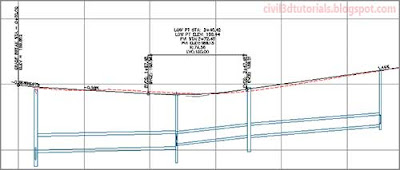
- In the Select Pipe Style dialog box, select C-STRM – Walls In Profile. Click OK. The appearance of the pipes in profile view changes so that the inside and outside pipe walls are shown (see Figure 14.17).
 |
| Figure 14.17 Pipes in profile view shown with inside and outside walls. |


