At times, you will find it easier to start with AutoCAD® commands to sketch your pipe network using basic entities. This approach works quite well because Civil 3D provides a command that will convert these basic entities to pipe networks:
the Create Pipe Network From Object command. This command will create pipe networks from Civil 3D alignments and feature lines as well. One disadvantage to this method is that the same parts are used for pipes and structures throughout the entire network. To create a pipe network from an object in your drawing, complete the following steps:
- Open the drawing named Creating Pipe Networks From Objects.dwg located in the Chapter 14 class data folder.
Tips:Make sure that your screen background color is set to white before continuing this exercise.
- In the left viewport, zoom in to the beginning of the Jordan Court alignment at the north end of the project. Note the heavy green polyline marked SAN that has been sketched in to represent the location of a new sanitary sewer pipeline.
- On the Home tab of the ribbon, click Pipe NetworkCreate Pipe Network From Object.
- Click the green polyline with the SAN labeling on it. Some black arrows should appear that point toward the south. These arrows indicate the assumed flow direction of the pipes.
- Press Enter to accept the current flow direction.
- In the Create Pipe Network From Object dialog box, do the following:
- For Network Name, enter Sanitary.
- For Network Parts List, select Sanitary Sewer.
- For Surface Name, select Road FG.
Tips:This surface will be used to automatically set the top elevations of the structures.
- For Alignment Name, select Jordan Court.
Tips:By referencing an alignment, you will be able to express the locations of pipes and structures using station and offset values.
- Check the box, next to Erase Existing Entity.
- Click OK.
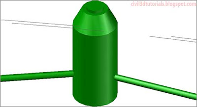
A new pipe network is created in place of the polyline. - In the bottom-right viewport, zoom in to one of the manholes. In plan view, the entities look rather simple, but in this view you see that they are actually 3D pipe and structure objects.
 |
| Figure 14.4 A 3D view of a pipe object and structure object. |
- In the left viewport, pan southward until you can see Madison Lane. Note the green polyline that starts near Madison Lane station 2+50 (0+080) and ends near Jordan Court station 21+50 (0+660).
- On the Home tab of the ribbon, click Pipe NetworkCreate Pipe Network From Object.
- Click the green polyline somewhere along Madison Lane. Some black arrows should appear that point toward the south. These arrows indicate the assumed flow direction of the pipes.
- Press Enter to accept the flow direction indicated by the black arrows
- In the Create Pipe Network From Object dialog box, do the following:
- For Network Name, enter Sanitary-2.
- For Network Parts List, select Sanitary Sewer.
- For Surface Name, select Road FG.
- For Alignment Name, select Madison Lane.
- Check the box, next to Erase Existing Entity.
- Click OK.
- Repeat steps 9 through 12 with the remaining polyline that begins at the Madison Lane cul-de-sac. This time use a Network Name of Sanitary-3. Now all of the sketch polylines have been converted to sanitary sewer pipes and structures.
- Pan and zoom within the lower-right viewport to inspect the pipes and structures in 3D. Notice that one of the pipes along Madison Lane is located at a much lower elevation than the others. This will be addressed later in this discuss.


