If you haven’t sketched the pipe design or when you want more control of the design as you go, the best choice is to create a pipe network by layout. This is done by using the Pipe Network Creation Tools command. After you launch this command and enter some information about the pipe network, you will be presented with the Network Layout Tools toolbar
(see Figure 14.5). This is similar to the toolbars you have used for other layout designs, such as creating alignments by layout or profiles by layout.
 |
| Figure 14.5 The Network Layout Tools toolbar. |
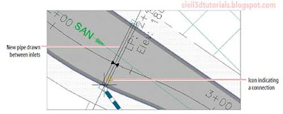
From the Network Layout Tools toolbar, you can choose pipes and structures from a parts list and then use commands on the toolbar to insert those parts into the drawing. You can change parts at any time and apply different types and sizes as you go. As you draw pipes and structures, special icons next to the cursor inform you when you are connecting parts to one another. For example,
Figure 14.6 shows a pipe being drawn between two inlets. The yellow icon indicates that the pipe will be connected to the inlet when the user clicks the mouse.
 |
| Figure 14.6 Icon indicating a connection between a pipe and structure. |
To create a pipe network by layout, follow these steps:
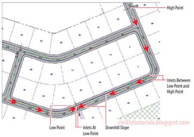
- Open the drawing named Creating Pipe Networks by Layout.dwg located in the Chapter 14 class data folder. In this drawing, red circles have been provided that indicate the locations of inlets. If you study the placement of these inlets, you will notice that some of them havebeen placed at low points, as indicated by the alignment labels. To prevent the inlets at the low points from being overloaded, additional inlets have been placed between low points and high points to collect some of the runoff. Figure 14.7 further illustrates inlet placement within the drawing.
 |
| Figure 14.7 Inlet placement. |
- On the Home tab of the ribbon, click Pipe NetworkPipe Network Creation Tools.
- In Create Pipe Network dialog box, do the following:
- For Network Name, enter Storm1.
- For Network Parts List, select Storm Sewer.
- For Surface Name, select Road FG.
- For Alignment Name, select Jordan Court.
- Click OK.
- You are prompted to specify a structure insertion point. In the left viewport, zoom in to the red circles at Jordan Court station 5+50 (0+170). On the Network Layout Tools toolbar, do the following (see Figure 14.8):
- To choose a structure, select Rectangular Junction Structure NF (SI)Curb Inlet from the first drop-down list.
- To choose a pipe, select Concrete Pipe (SI)15 Inch (400mm) Concrete Pipe from the first drop-down list.
 |
| Figure 14.8 The Network Layout Tools toolbar after selecting the structure and pipe. |
- Right-click the Osnap icon at the bottom of the screen, and then click Settings.
- On the Object Snap of the Drafting Settings dialog box, do the following:
- Check the box next to Object Snap On (F3).
- Click Clear All.
- Check the box next to Center.
- Click OK.
Tips:These settings will cause the Center object snap to be used each time you click a point in the drawing. This will help you do the next few steps a bit quicker.
- Click the center of the red circle to the east of station 5+50 (0+170).
- Click the center of the red circle to the west of station 5+50 (0+170).
- Pan northward until you can see the two red circles at the low point of station 2+40.42 (0+073.28). Click the circle to the south of the road.
- On the Home tab of the ribbon, click Pipe Network18 Inch (450mm) Concrete Pipe.
- Click the center of the red circle located north of 2+40.42 (0+073.28).
- On the Network Layout Tools toolbar, do the following:
- Choose the structure Cylindrical Junction Structure NF (SI)Storm Manhole.
- Choose the structure Concrete Pipe (SI)24 Inch (600mm) Concrete Pipe.
- Click the red circle on located at the western corner of the common area.
- On the Network Layout Tools toolbar, choose a structure of Concrete Rectangular Winged Headwall (SI)Winged Headwall for 24" (600mm) Pipe.
- Click the red circle on the opposite side of Emerson Road.
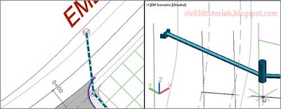
- Press Esc to end the command. You have created a storm sewer network, which discharges at a location across Emerson Road (see Figure 14.9).
 |
| Figure 14.9 A portion of the newly created storm pipe network. |


