To annotate a surface using spot elevation labels, follow these steps:
- Open the drawing named Labeling Surfaces.dwg or (Labeling Surfaces.dwg (METRIC)) located in the Exercise_04 class data folder. The top-right viewport is zoomed in to the north end of the project near the location where the magenta centerline meets the centerline of the existing road. Your task is to label the elevation of the existing road where these two centerlines meet.
- Click one of the contours to select the surface, and then click Add Labels ➢ Add Surface Labels on the ribbon.
- In the Add Labels dialog box, select Spot Elevation as the Label type.
- Verify that the spot elevation label style is set to Elevation Only–Existing and the marker style is set to Spot Elevation.
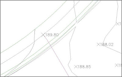
- Click Add. Snap to the northern endpoint of the magenta centerline. A label is placed at the location you selected (see Figure below).
 |
| Spot elevation label showing 189.80' (57.85m) added where the new road meets the existing road. |
- Keep this drawing open for the upcoming exercise.
A Note about Units
Throughout this discussion, you’ll notice that two values are provided for units of measurement. The first value is provided for the imperial system that is used in the United States, and the second value, in parentheses, is provided for the metric system that is used in many other countries. These values most often represent imperial feet and metric meters. It is important to note that, generally, only the numeric values are entered in the software, not terms like feet or meters. Also, you should know that the two numbers provided are not necessarily equal. In most cases, they are similar values that are rounded to work efficiently in their respective measurement systems.
 To annotate a surface using spot elevation labels, follow these steps:

