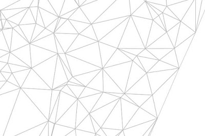
A surface in the Autodesk® AutoCAD® Civil 3D® program is generated using the principle of triangulation. At the very simplest, a surface consists of points. The computer generates a triangular plane using a group of three points. Each triangular plane shares an edge with another, and a continuous surface is made. This methodology is referred to as a triangulated irregular network (TIN), as shown in
Figure 1.
 |
| Figure 1: A triangulated irregular network or TIN. |
For any given (
x,y) point, there can be only one unique
z value within the surface (since slope is equal to rise over run, when the run is equal to 0, the result is “undefined”). What does this mean to you? It means surfaces created by Civil 3D have several rules:
- No Thickness
- Modeled surfaces can be thought of as a sheet draped over a surface; they have no thickness in the vertical direction associated with them.
- No Vertical Faces
- Vertical faces cannot exist in a TIN because two points on the surface cannot have the same (x,y) coordinate pair. Vertical walls or curb structures must have a slight offset of at least 0.001’ (0.0001 m); otherwise, they will appear flattened.
- No Caves or Tunnels
- The triangular planes that make up a TIN cannot overlap. If a design requires any tunnel-like structures, you will need to accomplish this with several surfaces instead.
There are four types of surfaces in Civil 3D:
TIN surfaces,
grid surfaces,
grid volume surfaces, and
TIN volume surfaces. A TIN surface is based on a set of points using Delaunay triangulation. A grid surface is based on a Digital Elevation Model (DEM) file consisting of a set of data points arranged in a regularly spaced grid configuration. DEM files can be obtained from various mapping agencies. Volume surfaces are built by measuring vertical distances between two surfaces. Volume surfaces can be created from two grid or two TIN surfaces.

