The option discussed here involves using user-defined properties on points to enter subsurface data. This option does not require any special downloads. In the following example, you will add user-defined properties to some soil boring points and leverage point groups to work with the data. The skills you learn in this example can be applied to multiple soil boring values for the purposes of creating subsurface data.
- Open the file 0309_SoilBorings.dwg or (0309_SoilBorings_METRIC.dwg).This file contains an existing ground surface together with the property linework for the site using Civil 3D Parcels.
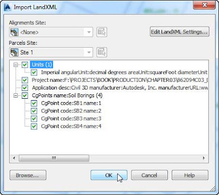
- Import into the drawing the soil boring points that are provided to you in a LandXML file byusing the LandXML tool that is on the Insert tab ➢ Import panel.The file that you will need is located in this data folder and is named 0309_SoilBorings.xml or (0309_SoilBorings_METRIC.xml).
Take a moment to examine the soil boring points and the current elevation listing.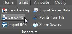
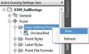
- From the Settings tab of Toolspace, expand the Point collection, right-click User-Defined Property Classifications, and select New.
- Name the new classification Soil Borings and click OK.
- Expand the User-Defined Property Classifications category (if it is not already expanded), right-click Soil Borings, and select New.
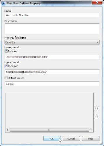
- Name the new property Watertable Elevation.
- Set Property Field Type to Elevation, uncheck Default Value, and then click OK.
- Jump back to the Toolspace ➢ Prospector tab and highlight the main Point Groups listing. At the bottom of Toolspace you will see a listing of all the point groups, as shown here.

- Set the classification as shown in the previous image.
- Right-click the Soil Borings point group and select Edit Points.
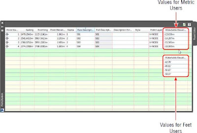
- Scroll over in Panorama until you locate the new classification column named Watertable Elevation.This is the information you added in the previous steps.
- Add the Watertable Elevation entries in Panorama, as shown here. Dismiss Panorama when you’ve finished.
- Right-click the Soil Borings group and select Properties. Switch to the Overrides tab, as shown here.
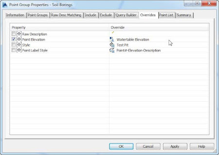
- Place a check mark next to Point Elevation on the Overrides tab.
- Click the tiny pencil icon twice or until it turns into the user-defined property icon. Initially the value will be <none>.
- Click the field next to the icon to set the value to Watertable Elevation.
- Click OK to dismiss the Point Group Properties dialog.
To compare your work with a completed example, see 0309_SoilBorings_FINISHED.dwg or (0309_SoilBorings_METRIC_FINISHED.dwg).
