In "
Designing New Terrain", if you completed the additional exercise, you created a new surface that represents the grading of individual lots. Had you continued working on this for a few hours, you would have eventually finished all of the lots, creating a surface that covered nearly the entire project. You also created a pond design that resulted in a surface of its own.
In "
Designing in 3D Using Corridors", surface to represent the model of the roads. This approach of designing the shape of the terrain in parts is common and recommended. For even the most talented designer, it is difficult to design all aspects of a project at once. It is easier, and often more efficient, to divide the design into “mini-designs” such as the road, lots, and pond that you experienced for yourself.
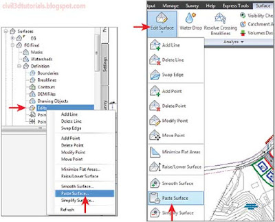
Once the parts are in place, it is then time to combine them into one “master” surface. To accomplish this, you use a simple but very powerful capability of surfaces in Civil 3D: pasting. Just as you are able to paste a paragraph of text into a document, you are also able to paste one surface into another. The similarities between surfaces and documents end there, however. For example, when you paste one surface into another, the pasted version is a “live” copy of the original, meaning that if the original is modified, the pasted version is modified also. To find the command to paste surfaces, right-click Edits within a surface in Prospector or choose the Surfaces ribbon tab
(See Figure 18.1).
 |
| Figure 18.1 The Paste Surface command found in a Prospector context menu (left) and the Surface ribbon tab (right). |
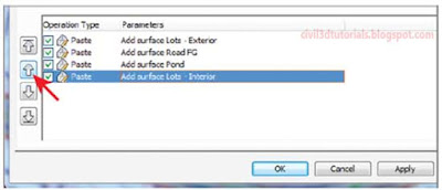
When working with multiple pasted surfaces, you can leverage the order in which they are pasted to achieve a desired result. The way this works is that when two overlapping surfaces are pasted, the second one will overwrite the first in the area where they overlap. The order in which surfaces are pasted can be controlled on the Definition tab of the Surface Properties dialog box
(See Figure 18.2). Here the order of operations can be rearranged, not just for pasting surfaces but for other operations as well.
 |
| Figure 18.2 The order of operations can be changed using the arrow buttons. This can affect the result of pasting multiple surfaces together. |
To see for yourself how to combine design surfaces, follow these steps:
- Open the drawing named Combining Surfaces.dwg located in the Chapter 18 class data folder. all of the lot grading design is complete, as shown by the blue, red, and green feature lines. There is also a small area between lots 73 and 76 where a grading group was used to calculate daylighting.
Tips:Make sure that your background color is set to white before completing the exercises in this chapter.
- In Prospector, expand Surfaces and note the surfaces that are listed there. Right-click Surfaces and select Create Surface. This opens the Create Surface dialog box.
Tips:All of the surfaces except EG have a style of _No Display assigned to them. That is why there are no design contours shown in the drawing.
- Enter FG Final in the Name field, and select Contours 1' and 5' (Design) (Contours 0.5m and 2.5m (Design)) as the style. Click OK. The new FG Final surface will be listed in Prospector.
- In Prospector, expand SurfacesFG FinalDefinition. Right-click Edits and select Paste Surface. The Select Surface To Paste dialog box opens.
- Select Lots – Exterior, and then click OK. Contours representing the grading for exterior lots appear in the left viewport. In the bottomright viewport, you see a 3D model of the interior grading. In the left viewport, zoom in to the interior lot area and note the haphazard contours extending across the road and through this area.
- Click one of the red or blue contours to select the surface, and then click Edit SurfacePaste Surface on the ribbon.
- Select Road FG and click OK. Within the road areas, the contours you saw in step 5 are replaced with contours that accurately represent the road elevations. In the 3D model, the roads are accurately represented and if you zoom in you can see the curb and the crown of the road clearly. The interior lot area is empty because this area has a hide boundary applied to it within the Road FG surface.
- Repeat steps 6 and 7, this time selecting the Pond surface. Contours now appear in the area of the pond, and the surface model reflects the shape of the pond.
- Repeat steps 6 and 7, this time selecting the Lots – Interior surface. Surface information is now shown for the interior lot grading, but the pond area has been overwritten with inaccurate information. You’ll fix this in the next few steps by changing the order in which the surfaces are pasted.
- Click one of the red or blue contours, and select Surface Properties on the ribbon. The Surface Properties dialog box opens.
- On the Definition tab, click Add Surface Lots – Interior and then click the up-arrow icon (see Figure 18.3). This moves the Lots – Interior surface above the Pond surface in the paste order.
 |
| Figure 18.3 Clicking the up arrow will change the order of operations so that the Lots – Interior surface is pasted before the Pond surface. |
- Click OK, and then click Rebuild The Surface. The lot grading contours and the correct pond contours are now shown. This is an example of the importance of managing the order of pasted surfaces to achieve the desired result.
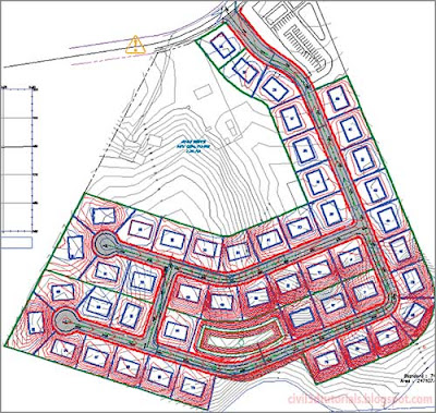
- Repeat steps 6 and 7, this time selecting the Lot Daylight surface. Contours are now shown in the area between lots 73 and 76, and all design grading for the project is now represented as one surface (see Figure 18.4).
 |
| Figure 18.4 Grading for the entire project is represented by one surface |
Modular Design
In the preceding exercise, you saw five design surfaces listed within Prospector, each representing its own mini-design. The origin of these surfaces is as follows:
- Lots - Exterior
- This surface is created from the feature lines used to grade all of the lots except those enclosed between Jordan Court, Madison Lane, and Logan Court. The feature lines were added to the Lots Exterior surface as breaklines. A polyline was drawn along the back edges of the lots and added to the surface as an outer boundary. The surface was allowed to triangulate across the road and interior lot areas. The following image shows the Lots - Exterior surface in 3D.
- Lots - Interior
- This surface is created from the feature lines used to grade all of the lots enclosed between Jordan Court, Madison Lane, and Logan Court. The feature lines were added to the surface as breaklines. A polyline was drawn along the front edges of the lots and added to the surface as an outer boundary. The surface was allowed to triangulate across the pond area. The following image shows the Lots - Interior surface in 3D.
- Pond
- This surface is created from the grading group used to design the pond south of lots 69 and 70. The following image shows the Pond surface in 3D:
- Road FG
- This surface is created from the road corridor. The following image shows the Road FG surface in 3D view:
- Lot Daylight
- This surface is created from a grading group used to design the daylighting between lots 73 and 76. It is shown in the following graphic in red along with the Road FG surface and Lot - Exterior surface in tan:In the preceding exercise, you combined all of these surfaces to create a single finished ground surface as shown in 3D view in the following image:


