Civil 3D styles provide a number of fundamental ways to display structures, fittings, and appurtenances. In plan view, you can display a structure as an outline of its 3D form, or you can use an AutoCAD® block as a symbol representing the structure. When you use a block, you can determine its size according to the drawing scale, a fixed scale, or the actual dimensions of the part.
Figure 6.1 shows a structure represented using an AutoCAD block on the left and as an outline of its 3D shape on the right.
 |
Figure 16.1 A structure shown as a block (left)
and as an outline of a 3D shape (right) |
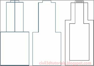
In profile view, there are three ways to display a structure: as a solid, as a boundary, or as a block.
- Solid
- The structure is shown as a slice through the 3D model of the part, which means that the size, shape, and dimensions are an accurate representation (see Figure 16.2, left). Any detail within the interior of the part is visible with this option.
- Boundary
- An outline of the 3D model of the part is shown (see Figure 16.2, center). This is also an accurate representation of the part but without the interior detail.
- Block
- A block (see Figure 16.2, right) is inserted and sized based on one of several options. The most common option is to scale the block vertically to match the height of the part and horizontally to match the width of the part. A block can provide the desired appearance of the part, but because of the horizontal and vertical scaling, it may not be an exact dimensional match to the actual part.
 |
| Figure 16.2 A structure shown as a solid (left), boundary (center), and block (right). |
For fittings and appurtenances, the plan view choices are Centerline, Catalog Defined Block, or User Defined Block.
- Centerline
- The structure is shown as a slice through the 3D model of the part, which means that the size, shape, and dimensions are an accurate representation (see Figure 16.3, left). Any detail within the interior of the part is visible with this option.
- Catalog Defined Block
- An outline of the 3D model of the part is shown (see Figure 16.3, center). This is also an accurate representation of the part but without the interior detail.
- User Defined Block
- A block (see Figure 16.3, right) is inserted and sized based on one of several options. The most common option is to scale the block vertically to match the height of the part and horizontally to match the width of the part. A block can provide the desired appearance of the part, but because of the horizontal and vertical scaling, it may not be an exact dimensional match to the actual part.
 |
Figure 16.3 A tee fitting shown as a centerline (left),
catalog defined block (center), and user-defined block (right). |
In profile view, there are no options for the display of fittings and appurtenances; fittings are simply represented as an outline, and appurtenances are represented by a symbol that resembles their type.
As a designer, it is not likely that you will be responsible for configuring styles or having to choose which display configuration to use—these things are typically taken care of by a CAD manager. However, knowing the ways in which structures, fittings, and appurtenances can be displayed will be helpful when you’re asking your CAD manager to build some styles for you.
To use styles to control the display of structures in your drawing, follow these steps:
- Open the drawing named Applying Structure and Fitting Styles.dwg located in the Chapter 16 class data folder. In the left view, the drawing is zoomed in to two manholes that are in close proximity to one another but do not appear to be conflicting. In the lower-right view, it appears that there could be a conflict, but at the current view angle, it is not absolutely certain.
- In the left viewport, click the Sanitary manhole (the one with the S inside the circle), and then click Structure Properties on the ribbon. This will open the Structure Properties dialog box.
- Click the Information tab, and then select C-SSWR - Outline as the style. Click OK. This style shows the outline of the actual 3D part, which reveals that the manhole is actually much larger than the symbol suggests.
- Press Esc to clear the selection of the sanitary manhole. Click the storm manhole (the one with the D inside the circle), and then select Structure Properties on the ribbon.
Tips:D is for drainage, a term that is often considered interchangeable with stormwater.
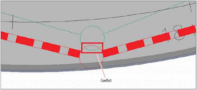
- Change the style of this manhole to C-STRM – Outline. With both manholes shown at their actual size, there is an obvious conflict (see Figure 16.4).
 |
| Figure 16.4 A conflict between two manholes is evident when the style reflects their true size. |
- Press Esc to clear the selection. In the left viewport, pan northward to the beginning of Jordan Court where the new water line ties to the existing water line. Click the tee fitting and the two elbow fittings near the connection point.
- Right-click and select Properties. Change the Style property to Water 3D. In plan view, the fittings now appear in their true 3D form as a result of the style change.
- Press Esc to clear the previous selection but keep the Properties window open. Pan northeast to the other corner of the Jordan Court – Emerson Road intersection, and select the storm manhole there.
- In the Properties window, change the style to C-STRM – MH Symbol Plan & Profile. As you select the new style, watch the manhole in the profile view in the top-right viewport to see its shape change slightly. This is because the block is not an accurate dimensional representation of the manhole. This may be acceptable for some instances, but when you need to see the exact dimensions of a manhole, you would use a different style.
It’s Not Called 3D for Nothing
The true form of a Civil 3D pipe or structure is a 3D object. For example, a manhole structure is typically some form of cylinder and is often somewhat complex, including tapers, eccentric cylinders, and so on. Some of the ways in which structures can be displayed involve slicing through this shape or showing an outline of it. In the following image, the same structure is shown from a 3D perspective (left), in plan view as an outline (center), and in profile view as a slice through the part (right). By using 3D representations of structures in your drawings, you can design more accurately and ensure that your structures are not conflicting with other underground objects.


