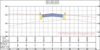
You may need to display additional information about the sections to accompany what is conveyed by the section view. Bands can be a useful tool for this purpose, enabling you to display information both graphically and textually. There are two types of section view bands, as described here:
- Section Data Bands
- You use this type of band for labeling offset and elevation data at regular increments along the profile view.
- Section Segment Bands
- You use this type of band to label length and slope information about the individual segments. Since the individual labels are created segment by segment, they are not evenly spaced across the band as you see in a section data band. Weeding can be applied to improve situations where segments are short and labels overlap.
To apply section view bands to section views, follow these steps:
- Open the drawing named Applying Section View Bands.dwg located in the Chapter 11 class data folder.
- Click the grid of the bottom section view, and select Section View Properties on the ribbon.
- On the Bands tab of the Section View Properties dialog box, do the following:
- For Band Type, verify that Major Stations is selected.
- Under Select Band Style, verify that Parallel With Tick is selected.
- Click Add.
- Change the Gap value for the newly added band to 0.
- Scroll right and select EG in the Section1 column.
- Click OK.
- The band is added, but there are values with lines through them at either end of the band. With the section view still selected, click Section View Properties on the ribbon once again.
- On the Bands tab of the Section View Properties dialog box, uncheck the boxes in the Label Start Offset and Label End Offset columns. Click OK. The labels at either end of the band are now omitted.
- Add a band showing the depth of the rock surface beneath the existing ground surface by applying these settings:
- Type: Section Data
- Style: Rock Depth
- Gap: 0
- Label Start Offset: Unchecked
- Label End Offset: Unchecked
- Section1: EG
- Section2: Rock
- Add a band showing offset values by applying these settings:
- Type: Section Data
- Style: Design – Offsets
- Gap: 0
- Label Start Offset: Checked
- Label End Offset: Checked
- Access the Bands tab of the Section View Properties dialog box once again. Click Save As Band Set.
- Enter Sta-Elev-Rock Depth in the Name field and click OK. Click OK to close the Section View Properties dialog box.
- Press Esc to clear the previous selection. Click the section view to the north, and then click Section View Properties on the ribbon.
- On the Bands tab of the Section View Properties dialog box, click Import Band Set. Select Sta-Elev-Rock Depth and click OK.
- Select EG for Section1 of the first two bands. Select Rock as Section2 of the second band. Click OK. The bands for this section view now match the bands of the section view that you modified in steps 2 through 7 (see Figure 11.7). This is the code that you will use.
 |
| Figure 11.7 A section view with bands added for existing ground elevations, rock depth, and offsets. |
- Repeat steps 10 through 12 to add the same band set to the third design section view.
- Press Esc to clear the previous selection. Zoom out and pan north to the sheets of section views. Click one of the section views, and then click View Group Properties on the ribbon.
- On the Section Views tab, click the ellipsis in the first row of the Change Band Set column.
- Click Import Band Set and select Section Sheets. Click OK until you have dismissed all dialog boxes and returned to the drawing. The bands have been added to the section views, but the section views must now be rearranged to account for the additional space that they occupy. You will address this in the next step.
- With one of the section views still selected, click Update Group Layout on the ribbon. Civil 3D automatically creates a fourth sheet as a result of this update (see Figure 11.8). This is the code that you will use.
 |
| Figure 11.8 A fourth sheet is created to accommodate the extra area taken up by the section view bands. |


