So far, you have seen that corridors can be sampled and shown in a cross-section view, but what about other sources of data? It turns out that sample lines can also slice through surfaces and pipe networks. In this section, you will learn how to sample and display data from these sources. In addition, you will learn how to add more sources of data to an established set of sample lines and section views so that you don’t have to start all over when new data becomes available.
To add more data sources to your drawing, sample them, and show them in section views, follow these steps:
- Open the drawing named Sampling More Sources.dwg located in the Chapter 10 class data folder.
- Click one of the section views in the upper-right viewport, and then click Sample More Sources on the ribbon.
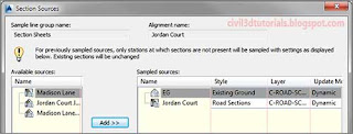
- In the Section Sources dialog box, click EG under Available Sources. Then click Add.
- Under Sampled Sources, verify that the style for EG is set to Existing Ground.
- Verify that the Section Sources dialog box looks like Figure 10.10, and then click OK. After a pause, a red dashed line is added to each section view. This line represents the surface of the existing ground. In addition, a default label set has been applied to the existing ground line, which is not appropriate for this application. You will remove the labels in the next several steps.
 |
| Figure 10.10 Sampling additional sources using the Section Sources dialog box. |
- With the section view still selected, click View Group Properties on the ribbon. This opens the Section View Group Properties dialog box.
- On the Sections tab, click <Edit> in the Change Labels column next to EG.
- Select _No Labels and click OK. Click OK again to close the Section View Group Properties dialog box and return to the drawing. The labels should be removed.
- In the top-right viewport, zoom in to the first section view at 0+50 (0+010) in the lower-left corner of the first sheet. Pan upward and examine each section view. When you get to the top of the column, move to the bottom of the next column and pan upward to continue viewing the sections in order. As you do this, try to visualize traveling down the road and experiencing the changes in the road geometry that you see from section to section.
- On the Insert tab of the ribbon, click LandXML.
- Browse to the Chapter 10 class data folder, and select Preliminary Waterline.xml. Click Open.
- Click OK to dismiss the Import LandXML dialog box. A new pipe network representing the preliminary design of the waterline along Jordan Court has been created in the drawing. If you zoom in to the plan view of Jordan Court, you can see the double blue line along the right side of the road.
Tips:The scenario here may be that an engineer has asked you to check the waterline design against your road design to see if there are any problems.
- Click one of the section views, and then click Sample More Sources on the ribbon.
- In the Selection Sources dialog box, click Preliminary Waterline and then click Add. Click OK to close the dialog box.
- Press Esc to clear the selection of the section view. Zoom in and examine the section views to verify that the waterline is being shown. As you look at the section views, do you see any problems with the location of the waterline?
- Use the LandXML command to import Subsurface Rock.xml.
- Use the Sample More Sources command to add the new surface named Rock to the section views. Set its style to Rock.
- Once again, you need to clear away the labels. Click a section view, and then click View Group Properties on the ribbon.
- Click <Edit> in the Change Labels column next to Rock. Select _No Labels and click OK. Click OK again to return to the drawing.
- Study the section views again. In a real-life situation, you may need to inform the engineer that the waterline design requires the excavation of a significant amount of rock. Also notice that around station 9+00 (0+270), the rock layer is very close to the surface—you may want to consider raising the road a bit in this area to avoid costly rock excavation.
What Do You See?


