 |
| Figure 9.14 The Target Mapping dialog box showing the three types of corridor targets along with the subassemblies that can use each type of target |
To assign targets to the corridor that will provide daylighting and create a turn lane, follow these steps:
- Open the drawing named Applying Corridor Targets.dwg located in the Chapter 09 class data folder.
- Click the corridor in the drawing, and then click Edit Targets on the ribbon.
- When prompted to select a region, click inside the left viewport anywhere within the corridor. As you do, you should see a blue outline appear around the corridor.
- In the Target Mapping dialog box, under Width Or Offset Targets, click <None> in the Object Name column next to the Left Lane subassembly. This will open the Set Width Or Offset Target dialog box.
- In the Set Width Or Offset Target dialog box, under Select Object Type To Target, select Feature Lines, Survey Figures, and Polylines.
- Click Select From Drawing. Then in the left viewport, zoom in to the beginning of Jordan Court where it intersects with Emerson Road.
- Click the red polyline that represents the desired path of the left lane’s edge, and then press Enter.
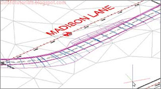
- Click OK twice to return to the drawing. The corridor is widened near the entrance, as shown in Figure 9.15. By widening the left lane in this way, you make extra room for a turning lane.

Figure 9.15 The corridor is wider where the lane edge polyline was targeted. - Click within the corridor to reopen the Target Mapping dialog box.
- In the Target Mapping dialog box, click the cell next to Surfaces that reads <Click Here To Set All>
- Pan around in the lower right viewport to view the 3D representation of the corridor. Select EG and click OK. Then click OK to dismiss the Target Mapping dialog box. You should now see additional geometry along the edges of the corridor (see Figure 9.16). This represents the daylighting that has been applied. The daylighting geometry is noticeably wider in some areas than in others. These are areas that are below existing ground through which a ditch has been constructed. This automatic creation of ditches is a function of the BasicSideSlopeCutDitch subassembly.

Figure 9.16 Areas of daylighting along the corridor.

Corridor Region
In step 3, you are prompted to select a region to edit. A region is essentially a part of your corridor that begins at one station and ends at another. All corridors start out with a single region that extends the full length of the corridor. This is the condition of the example corridor right now. As a design evolves, however, you will probably break up the corridor into multiple regions. This will be covered in more detail a bit later in this chapter.
Download Exercise File :
