Earlier, in the section “Connecting Objects to Objects”, you observed how a profile, road design, and pipe system design could be related to one another. Now, imagine a design team where Joe designs the profile in one drawing, Susan designs the road model in another drawing, and Jill designs the pipe system in yet another. Data shortcuts make it possible for these designs to be linked together just as you witnessed earlier—even across drawings.
A data shortcut is a link to a Civil 3D object that enables another drawing to get access to that object. For example, if you create a profile that represents the proposed centerline elevations of a road, you can publish a data shortcut for that profile, which becomes “visible” to other drawings. You or someone else can then open another drawing and use that data shortcut to access the profile. Once you have accessed the profile, you can use it as part of another design, such as the case with the road model.
When a data shortcut is created, it is displayed in Prospector beneath the Data Shortcuts heading. Data shortcuts are stored within a data shortcuts projects folder. This enables related data shortcuts, such as those pertaining to a given project, to be grouped together in one location. The folder that contains data shortcuts folders is the working folder. It allows you to set up one location where all projects are stored.
 |
| Data shortcuts shown within Prospector. |
 |
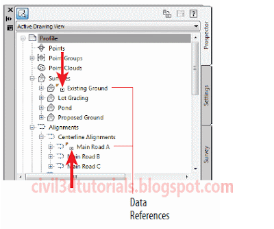
| A surface data reference and an alignment data reference shown along with other surfaces and alignments in Prospector. |
- Open the file named Surface.dwg or (Surface.dwg (METRIC)) located in the Exercise_02 class data folder.
- If the Toolspace is not visible, click Toolspace on the Home tab of the ribbon.
- On the Prospector tab of Toolspace, right-click Data Shortcuts and select Set Working Folder. The Browse For Folder dialog box opens.
- Browse to the Exercise_02 class data folder, and select Sample Working Folder. Click OK.
- Right-click Data Shortcuts, and select New Data Shortcuts Project Folder. The New Data Shortcut Folder dialog box opens.
- Type Sample Project in the Name field and click OK.
- Save the drawing. Click the Manage tab of the ribbon, and then click Create Data Shortcuts. The Create Data Shortcuts dialog box opens.
- Check the box next to Existing Ground and click OK.
- Open the file named Alignment.dwg or (Alignment.dwg (METRIC)) Exercise_02 class data folder.
- Repeat steps 7 and 8 for the alignment named Main Road A.
- Open the file named Profile.dwg or (Profile.dwg (METRIC)) Exercise_02 class data folder.
- On Prospector, expand Data Shortcuts ➢ Surfaces. Right-click Existing Ground, and select Create Reference.
- Click OK to accept the default settings on the Create Surface Reference dialog box. Contours in the drawing indicate a newly added surface.
- Repeat steps 12 and 13 for the alignment data shortcut named Main Road A. A new alignment is created in the drawing.
- On the Home tab of the ribbon, click Profile ➢ Create Surface Profile. The Create Profile From Surface dialog box opens.
- Click Add, and then click Draw In Profile View. The Create Profile View – General dialog box opens.
- Click Create Profile View. Pick a point in the top-right viewport. A new profile is created that is the result of relating an alignment to a surface.
This profile represents the interaction between three different drawings.
A profile created from an alignment data reference and a surface data reference.


A Note about Units
Throughout this chapter, you’ll notice that two values are provided for units of measurement. The first value is provided for the imperial system that is used in the United States, and the second value, in parentheses, is provided for the metric system that is used in many other countries. These values most often represent imperial feet and metric meters. It is important to note that, generally, only the numeric values are entered in the software, not terms like feet or meters. Also, you should know that the two numbers provided are not necessarily equal. In most cases, they are similar values that are rounded to work efficiently in their respective measurement systems.
