Another way to create pressure networks is using the Pressure Network Creation tools command. When you launch this command, a specialized ribbon tab
(see Figure 15.4) opens that contains tools for pressure network layout. From this specialized ribbon tab, you can choose the pipes, fittings, and appurtenances from the parts list and use the commands on the ribbon to insert those parts into the drawing. You can change parts at any time and apply different types and sizes as you go.
 |
| Figure 15.4 The specialized ribbon tab for pressure network layout. |
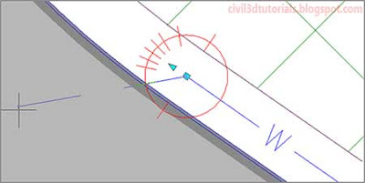
To guide your design, Civil 3D provides a compass
(see Figure 15.5), which displays the bend angles and deflections available at a given point, based on information stored within the parts list. The compass will automatically “snap” your cursor to an available bend angle to prevent you from laying out a nonstandard bend in the pipeline.
 |
| Figure 15.5 The compass (the red circle) shows the available bend angles and deflections. |
Another fundamental difference with pressure network layout is that you provide a value for
cover and Civil 3D will automatically set the elevation at each end of a pipe according to that value. You can change the cover value as you design.
To create a pressure network using the layout tools, follow these steps:
- Open the drawing named Creating Pressure Networks by Layout.dwg located in the Chapter 15 class data folder. In this drawing, red circles have been provided to indicate the locations of bends.
- On the Home tab of the ribbon, click Pipe NetworkPressure Network Creation Tools.
- In the Create Pressure Pipe Network dialog box, do the following:
- For Network Name, enter Water Main.
- For Network Parts List, select Water Supply.
- For Surface Name, select Road FG.
- For Alignment Name, select Jordan Court.
- Click OK.
- The Pressure Network Plan Layout ribbon tab opens. Do the following:
- On the Network Settings panel, enter 4.5 (1.5) for Cover.
- Under Select A Size And Material, select 6 INCH (150mm) DUCTILE IRON.
- Click Pipes Only. Snap to the center of the circle marked A; then snap to the center of the circle marked B. Notice the compass that appears at point B that shows the allowable deflection at the pipe joint and restricts the ability to draw the next pipe to stay within that allowable deflection.
- At the command line, click Curve to apply the Curve option. Snap to the center of the circle marked C.
- At the command line, click Straight to apply the Straight option. Snap to the center of the circle marked D.
- On the ribbon, to the right of Add Fitting, select 6 INCH (150mm) ELBOW 90 DEG. Click Add Fitting. Snap to the end of the last pipe that you drew. A new 90° fitting should be placed at the end of the pipe, but it curves in the wrong direction.
- Press Esc to end the current command. In the lower-right viewport, zoom in to the area where you inserted the fitting so that you can observe the development of the design in 3D. In the left viewport, click the new fitting and then click the northward-pointing arrow grip to flip the fitting so that it curves toward the southwest. Press Esc to clear the selection of the fitting.
- Click Pipes & Bends on the ribbon. In the left viewport, click the 90° elbow and then snap to the center of the circle marked E. Notice the difference in the compass, which now shows available bend angles rather than deflections. The available angles are based on the fittings listed in the parts list.
- On the command line, click Curve to apply the Curve option. Click a point somewhere between circles E and F; then snap to the center of circle F. Press Esc to end the command. A new 90° elbow has been inserted, and a curved section of pipe has been drawn from circle E to circle F (see Figure 15.6).
 |
| Figure 15.6 The newly drawn waterline including the 90° elbow at circle E, and the curved section of pipe between circles E and F. |


