The most common use of parcel segment labels is to provide numerical information that defines the geometry of property boundaries. This numerical information appears as bearings and distances for line segments and curve data for curve segments. When an adequate numerical description of a parcel is provided, the parcel can be re-created either on paper or in the field.
To add labels to parcel segments, you use the Add Labels command. You can label the segments one by one, or you can provide labels for all of the segments that make up a parcel.
Curve Data
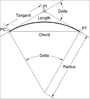
There are many geometric properties that can be used to define a curve. The most common properties are shown in the following drawing and then described:
- Length: The length of the curve measured along its arc.
- Radius: The distance from the center point of the curve to a point on the curve.
- Chord: The straight line from the beginning point of the curve to the ending point of the curve. The bearing and distance of this line can be labeled.
- Delta: The change in direction between a line tangent to the curve at its beginning point and a line tangent to the curve at its ending point.
- Tangent: The distance between the point of curvature (PC) and the point of intersection (PI) or between the point of tangency (PT) and the PI.
Depending on the requirements, you may need to include different combinations of these curve dimensions. Typically, you must create multiple curve dimension labels in order to provide enough information to reconstruct the curve.
To use parcel segment labels to provide bearings, distances, and curve data in your drawing, complete the following steps:
- Open the drawing named Creating Parcel Segment Labels.dwg located in the Chapter 13 class data folder.
- Zoom in to lots 32 and 33 near the center of the project
- On the Annotate tab of the ribbon, click Add Labels.
- In the Add Labels dialog box, select Parcel as the feature. Click Add.
- Click the north side of lot 33. A new bearing and distance label is added.
- Click the east and west sides of lot 33. Two more bearing and distance labels are created.
Tips:The labels will be created at the location you click, so you should click near the midpoint of the line.
- Pan south to lot 69, and click the curve that makes up the south boundary of lot 69. A curve label is created that displays the delta, length, and radius.
- In the Add Labels dialog box, select Multiple Segment as the label type and then click Add.
- Click the parcel area label for lot 32. When you’re prompted to select a direction, press Enter to accept the default direction of clockwise. All segments for lot 32 are labeled simultaneously.
Labeling Lines and Curves
Thus far in this discuss, you’ve learned how to label parcel segments, but what about plain old lines, arcs, and polylines? Do these entities have to be converted to parcel segments in order to be labeled? The answer is no. Civil 3D enables you to label basic AutoCAD® entities using the same Add Labels command that you used for labeling parcel segments. Just remember that you need to choose Line And Curve as the feature in the Add Labels dialog box, as shown here.


